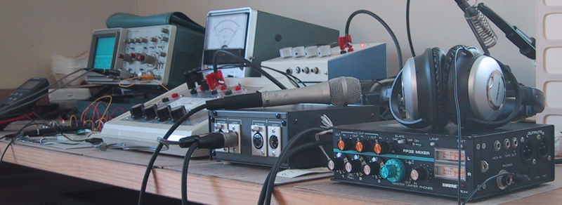

In this page I'll introduce a new topology for audio oscillators which I call the Sallen-Key oscillator. I'll show a detailed schematic for a tone generator that runs on as little as 1.5 Vdc, using the Sallen-Key configuration. And finally, I'll apply the tone generator to implement a phantom powered signal source for testing balanced microphone inputs.
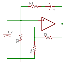
Textbooks and web pages usually show the Wien Bridge configuration when describing single-opamp audio oscillators. The Wien Bridge circuit shown in sketch form below will oscillate at a frequency equal to 1/(2π RC) where R = R1 = R2, and C = C1 = C2.
|
Oscillation will be self-starting when overall gain is greater than 3, so we want (R3/R4 + 1) > 3, or R3/R4 > 2. Once oscillation begins, additional circuit elements must be brought into play to maintain a constant output level with low harmonic distortion. Tuning this kind of oscillator is complicated by the fact that the amount of gain required to maintain stable oscillation depends on how closely the tuning resistors and capacitors are matched. This is why the output level of an RC (resistance-capacitance) oscillator bounces around so much when setting the frequency. If you need a tunable single-opamp RC oscillator, then you need to take special care to be sure that R's and C's remain equal as they are varied.
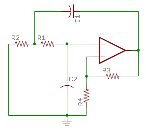
Here I'll diverge from standard practice and introduce a new circuit for RC oscillators. Based on the Sallen-Key equal-component-value second-order LP (low-pass) filter, my new circuit is nothing more than an LP filter with the input grounded. Because it is second-order, this circuit has the capacity for sustained oscillation built in, which designers normally try to avoid. Frequency is the same as for the Wien Bridge oscillator, which is 1/(2π RC) where R = R1 = R2, and C = C1 = C2. The condition for oscillation is also the same as for the Wien Bridge configuration, which is an overall gain greater than 3. Actually, most operating parameters of this new circuit are similar to the Wien Bridge oscillator. We'll need to add a circuit which starts up with gain slightly greater than 3, and then maintains gain at exactly 3 once the sine wave output reaches the desired level.
|
My idea in thinking of the Sallen-Key architecture was that since it is already an LP filter, it should naturally suppress distortion in the form of harmonics, which are by definition above the fundamental. The LP filter and the oscillator are each tuned by the same two resistors and two capacitors, so that whenever you change the oscillation frequency, you have already tuned the LP filter at the same time. Near the oscillation frequency, both BP (band-pass) and LP filters exhibit high 'Q' and steep skirts. Far from the oscillation frequency however, their responses are quite different. The BP filter ultimately falls off at 6 dB/8va while the LP filter falls off at 12 dB/8va on the high side, potentially offering much better suppression of higher harmonics. If I get a chance to study this effect in detail I'll report my results here.
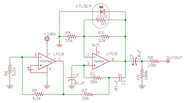
I had in mind to design a tone generator which could operate on just two 'N' cells in series, a total of +3.0 Vdc. But running to end-of-life for the batteries would mean operating on as little as +1.5 Vdc. So I started with Bob Widlar's LM10 opamp and voltage reference which comes in an 8-pin DIP package from Texas Instruments and is available from distributors like Digikey. This IC (integrated circuit) features a rail-to-rail main output, a common mode input range that includes ground, and it can be connected to single-polarity power supplies ranging from +1.2 Vdc up to +40 Vdc.
|
I chose an output level of -10 dBu for this circuit, or 245 mVac. This is a standard level used in home hi-fi and amateur recording equipment, and can be connected directly to any RCA input jack. Output swing for this level is 0.7 Vpp, which is well within reach for the LM10, even when powered at the minimum supply voltage. Note however that the LM10 inputs aren't rail-to-rail. In the detailed circuit shown above I allow the natural gain of 3 to extend down to DC, so that the opamp inputs at pins 2 and 3 sit at around +0.36 Vdc, while the output at pin 6 sits at about +1.08 Vdc. Adding half the peak-to-peak swing of the sine wave to this gives +1.43 Vdc, which just begins to light LED1 in the optoisolator. At startup the LED is dark, leaving the overall gain set by R3 and R4 at (1 + 33/15) or times 3.2 which allows oscillations to ramp up. In steady state operation at -10 dBu the LED is lit briefly at the top of each cycle, keeping average gain at exactly 3. The parallel contribution of R7, an LDR (light dependent resistor) inside the optoisolator, is about 330k.
The VTL5C4 Vactrol optoisolator is a standard part in audio applications, having a reasonable compromise between speed, sensitivity, distortion, temperature dependence, and history dependence. This was previously manufactured by Vactec, then EG&G, and then Perkin-Elmer, but is currently made by Excelitas Technologies, and is available from distributors like Allied Electronics. I had three on hand and found them to be more or less interchangeable in this application, although harmonic distortion varied from -50 dB (0.32%) to -55 dB (0.18%). I found that by fiddling with the startup gain (that is, the ratio of R3/R4) I could reduce distortion to below -60 dB (0.1%), but felt that this unnecessarily risks having a circuit that might not start up at all under some conditions. There are actually several distortion mechanisms at work in this circuit. First the LDR itself isn't precisely Ohmic, meaning that current through the LDR isn't exactly proportional to the voltage across it. At the signal levels present here however, this will typically be -80 dB or more below the fundamental, less than 0.01%. The LM10 opamp will have some inherent non-linearity, which is probably below the noise floor in this case. But the most prominent source of distortion in the output is the intermittent nature of illumination in the optoisolator. The LED is lit only at the top of each cycle, and the LDR then has to "carry over" any change in gain until the next cycle. So the gain change occurs as a short bump followed by a longer slide, all determined by the rising and falling time constants of the LDR. This periodic gain change is effectively a multiplication, which introduces harmonically related distortion products into the output.
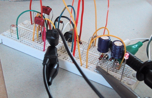
Frequency of oscillation is determined by the equal-value capacitors C1 and C2, and by equal-value resistors R1 and R2. Here I chose an operating frequency of 440 Hz, which is a standard 'A' for tuning musical instruments. Note that in the Sallen-Key oscillator (and most other single-opamp RC oscillators as well, including the Wien Bridge) the frequency determining components are not ratiometric. That is, the frequency does not depend on the ratio of similar parts, but rather on the absolute value of each part. This is the worst case in terms of designing for temperature stability, so you just have to buck up and pay the price for high-stability resistors and capacitors if you want accurate frequency. I used generic 1/4 Watt 5% film resistors and Panasonic P-Series polypropylene 2% capacitors, and achieved temperature stability of about 0.21 Hz per °C over the range from 5 °C to 35 °C. Frequency can be tuned by varying either R1 and R2, or C1 and C2, but since trimmers are notoriously temperature dependent, I decided to solder in fixed components for this adjustment. Using fixed components also sidesteps the problem of obtaining ganged pairs of trimmer resistors or capacitors. To set the frequency accurately you'll need either a high-resolution frequency counter or a precision frequency reference. Note that 60Hz from a filament transformer is quite precise, and is a rational sub-multiple of 440 Hz. Just set up a Lissajous pattern on your oscilloscope and adjust for the ratio 22/3. If you really want to tune up with this circuit, you'll need to be within less than +/- 1 cent, or within 0.25 Hz of 440. That means less than one beat in 4 seconds when compared to a trusted reference. Note that stray capacitance can easily detune the tone generator by a slight amount, so this circuit should always be used inside a shielded enclosure. Using the components I chose for R1, R2, C1, and C2, I'll have to stay within +/- 1 °C of room temperature to have a usable reference. I think it's time for an upgrade!
I was pleasantly surprised to find that output level stayed within about 1 dB over the temperature range of 5 °C to 35 °C, decreasing at around -0.035 dB per °C. Output level is determined by the forward voltage of LED1 and the average DC voltage on pin 6, which is in turn set by the ratio of R5/R6. The value of the LM10's internal reference is 200 mV +/- 10 mV, so some adjustment is likely. I started with R5 = R6, and then added parallel resistance across R5 until the output level was 245 mVac. Notice also the output network consisting of C3, R8, and R9. This is in place to block DC from the LM10 output pin, and to isolate the LM10 from capacitive loading by, for instance, a coaxial cable. For battery powered devices, I like to think in terms of AH (Amp-hours) of capacity. Note that when multiple cells are in series, all of them carry the same current, so the total AH capacity of the stack is the same as the capacity for each individual cell. In very round numbers I think of 'AA' cells as having 2 AH capacity, 'AAA' cells having 1 AH, and 'N' cells having 1/2 AH. Actual results depend on many things, but in this case I would estimate that my Sallen-Key tone generator, which draws about 320 uA independent of supply voltage, will run for at least 1500 hours on a fresh set of alkaline 'N' cells. Alkaline batteries are ideal in this application, because of their long shelf life with intermittent use.
| Parameter | Measured Value |
|---|---|
| Output Amplitude | -10 dBu (245 mVac) |
| Amplitude Stability | -0.035 dB per °C |
| Total Harmonic Distortion | -50 dB (0.32%) |
| Output Frequency | 440 Hz |
| Frequency Stability | +0.21 Hz per °C |
| Supply Voltage Range | +1.5 to +40 Vdc |
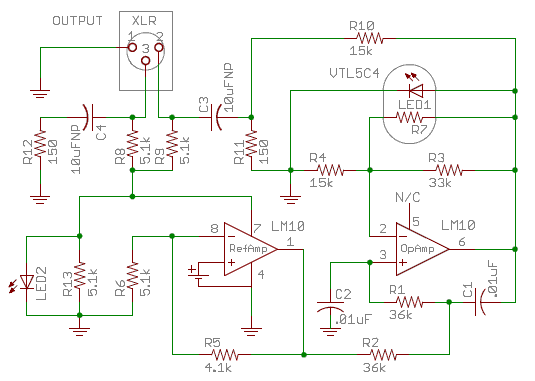
The low power/low voltage tone generator we've just developed seems ideal for phantom power applications. I'm speaking here of the so-called "P48" or "simplex" scheme where a power supply voltage of up to +48 Vdc is applied to both sides of a balanced microphone input through a pair of current limiting series resistors. It is possible to obtain up to about 10 mA at 10 Vdc, to power outboard circuits consuming up to 100 mW of power. We won't need quite that much power, but the following detailed schematic shows an XLR connector with resistors R8 and R9 situated to pick off phantom power coming in from the mic preamp.
|
This is regulated by LED2 to about +1.8 Vdc. No further regulation or bypassing is required, as LEDs typically have a low dynamic impedance. LED2 will be carrying slightly more than 5 mA and can be used to indicate the presence of phantom power. Note that the forward voltage of an LED depends on the forward current as well as on the LED color. In this application we are relying on these variables to ensure that the forward voltage of LED2 is always greater than the forward voltage of LED1 in the optoisolator. If you need to boost up the supply voltage at pin 7 on the LM10, you can try a different color of LED, switch to a high-brightness type, or add a rectifier diode forward-biased in series with LED2. Resistors R11 and R12, and non-polarized electrolytic capacitors C3 and C4 establish balanced low-impedance AC paths to ground from both input pins. C3 and C4 should be rated for 50 Vdc in either direction, to be sure they can block the +48 Vdc phantom power. The AC impedance seen by the mic preamp will be about 300 Ohms. The 10 uF value of C3 and C4 is adequate since only our 440 Hz signal will be present. If lower frequencies are to be handled these capacitance values must be increased accordingly. Resistor R10 brings in the sine-wave signal from the tone generator and injects it into the non-inverting input at pin 2 on the XLR connector. The sine-wave signal is attenuated by about a factor of 100 by the resistive divider consisting of R10 and R11. So our -10 dBu signal becomes -50 dBu or 2.5 mVac, about the same signal level one would expect when talking into a low-impedance dynamic microphone. Resistor R13 has been added to allow a discharge path to ground for what are often rather high valued electrolytic capacitors filtering phantom power in the mic preamp. If you want the option of choosing battery power or phantom power, a SPDT (single-pole double-throw) switch can be fitted to connect LM10 pin 7 to either a two-cell battery stack, or to phantom power at LED2.
| Pin# | LM10 Pin Name | DC Voltage |
|---|---|---|
| 1 | reference output | 0.345 |
| 2 | opamp inverting input | 0.345 |
| 3 | opamp non-inverting input | 0.343 |
| 4 | ground | 0.000 |
| 5 | balance | 0.034 |
| 6 | opamp output | 1.044 |
| 7 | positive supply | 1.778 |
| 8 | reference feedback | 0.193 |
I am placing the circuit ideas and schematic diagrams presented on this page in the public domain, for the benefit of hobbyists and engineers. Please remember that only you can determine if these ideas are suitable for your application. Feel free to post a link to this page on your site, but please don't copy my content. This page should be available at this URL for the foreseeable future. I claim a trademark interest in the names "Williamsonic" and "www.williamsonic.com".

