Active filters for audio use are commonly described by a second order transfer function, shown here in its most general form:

This transfer function can be used to model the behavior of systems described by a second order linear differential equation1. To obtain the amplitude and phase response with respect to frequency of a proposed filter design, you replace the Laplace variable 'S' with complex frequency and plot the result. While this can be a tedious task if done by hand, off-the-shelf computer software like MS Excel can be used to perform the calculations and plot the results, as shown below.
Click here to open an MS Excel spreadsheet containing the calculations for frequency response of a state variable filter. If your browser is configured right, it should automatically launch Excel and open the sheet. It may also open a blank spreadsheet in front of mine, which you will need to close. You should then be able to select "File/Save As..." to create a copy on your local hard disk. Before you can recalculate the sheet, you must have the "Analysis Tool Pack" enabled. The default is for it to be disabled, so you will likely have to manually enable it.
Once you have the spreadsheet open, you will see the numerator and denominator coefficients at the upper left of the sheet. Just type new values into these cells, and the filter frequency response will be replotted in a few seconds. While denominator coefficients should always have positive values for filters that don't oscillate, numerator coefficients may be positive, zero, or negative depending on the effect you want. For unity gain applications, the 'a2' value should be set to '1'. The spreadsheet is normalized to a center frequency of 1 radian/sec. However, with a little work, you can modify the sheet to show any center frequency you want.

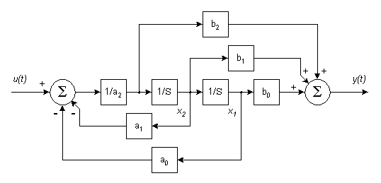
When it comes to actually implementing state variable filters, you have a number of choices. One of these is the Control Canonical form shown in the simulation diagram above. The simulation diagram is an important stepping stone to take you from trasfer function to schematic diagram. It conforms mathematically to the transfer function, while showing each of the signals needed and their relationship to each other. The simulation diagram is made of three types of blocks: integrators, summers, and gain(loss) blocks. Two integrators are shown, their outputs are identified by the state variables 'X1' and 'X2'. Two summers are shown, one at the input 'U(t)' and one at the output 'Y(t)'. Gain(loss) blocks are shown for each transfer function coefficient.

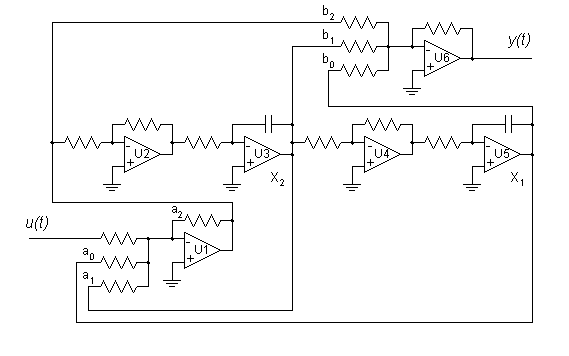
The schematic above shows one possible implementation of the Control Canonical simulation diagram. Of course, many other configurations are possible. Most published designs combine various functions to reduce the number of opamps. I've left all the functions separate for maximum flexibility in breadboarding. Once you have a filter you like, you can always combine functions to reduce parts count. Start with all resistors at 10k and the two integrating capacitors at 10nF for a center frequency of 1600 Hz. I usually use 10k DIP resistor networks, because they are closely matched, and track well with age and temperature. I like the LF353 dual JFET opamp from National Semiconductor, but you can use any unity gain compensated opamp rated for audio use. The circuit as shown will produce a flat response across the audio range. Not much of a filter, but at least it proves you wired your breadboard correctly.
Now try disconnecting the 'b0', 'b1', and 'b2' signals one at a time from the output summer U6 and see what happens to frequency response. To increase the 'Q' of the filter, increase the value of the resistor at 'a1'. Change center frequency by changing the time constant (resistance, capacitance, or both) of both integrators. Changing the time constant of just one of the integrators will adjust the center frequency, but will affect other parameters as well. An interesting feature of the Control Canonical form is that a separate output is available for each numerator coefficient. This is commonly used to produce a universal filter with separate high pass ('b2'), band pass ('b1'), and low pass ('b0') outputs. You can mix the outputs in various ratios to obtain other filter types as well. Opamp U6 is shown in the schematic for this purpose. One use for this type of filter is designing active crossovers which divide an audio signal into several bands which are then amplified separately and sent to separate loudspeaker drivers.

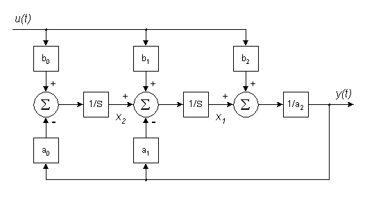
A complement to the Control Canonical form is the Observer Canonical form shown above. While it is still mathematically equivalent to the general second order transfer function, its inputs and outputs are configured quite differently from the Control Canonical. Also, one additional summer is required.

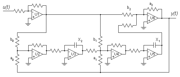
Here is one possible implementation of an Observer Canonical state variable filter. Again, the integrator outputs are identified by the state variables 'X1' and 'X2'. This time, however, the numerator coefficients each have their own input instead of output. I've shown opamp U1 driving all three inputs to keep the circuit non-inverting overall, but you can drive each of the inputs from different sources. You can design a parametric equalizer for audio use by providing separate gain controls for each numerator coefficient.
The schematic diagrams I've shown here are somewhat more complex than the usual published filter designs. So why should you use state variable designs for your active filters? I can think of a number of reasons.

