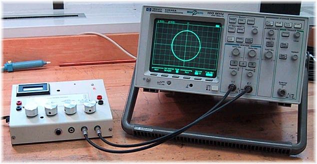
On this page, I'll show the major functional blocks necessary to design a general purpose audio oscillator, and give all the details of my current prototype. Implementation is in the mode of an analog computer, since the desired outputs are sine and cosine values as a function of time. The following snapshot shows my prototype connected to an X-Y oscilloscope, to display a Lissajous pattern. The circle shown on the scope indicates a nearly perfect 90 degree phase shift between sine and cosine outputs. This quadrature relationship is maintained across the frequency range of the oscillator.

I've always been fascinated by oscillators, because so many of my past breadboards oscillated but shouldn't have. And even when I want a circuit to oscillate, it often seems to be out of control. I have found that a number of authors, including Bob Metzler1 and Don Lancaster2, identify the state variable oscillator as the circuit of choice for generating low distortion sine waves for audio use. These authors don't show the details of how to implement such a circuit, but luckily one day while surfing the web I came across a reference to the article "Design for a Low-Distortion, Fast-Settling Source" in the August 1980 issue of the Hewlett-Packard Journal3. That article describes the internal workings of the HP8903A Audio Measurement System, including sketch schematics. Based on this information, I have been able to develop the following analysis.
The stability of a second order feedback control system is often described by the characteristic equation of the system:

When described in this form, it can be shown that  is the natural frequency and
  is the damping factor of the system. So to make an audio oscillator, you design a system (an electronic circuit in this case) with
  equal to the desired output frequency, and
  equal to zero so the oscillations are undamped.
The electronic circuit needed to satisfy this equation is a simple analog computer having two integrators and a summer, as shown in this simulation diagram. The integrator outputs are identified by the state variables x1 and x2.
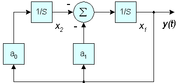
Set the coefficient a0 to unity, and adjust a1 to start and maintain oscillation. You can breadboard this simple schematic to prove out the technique.
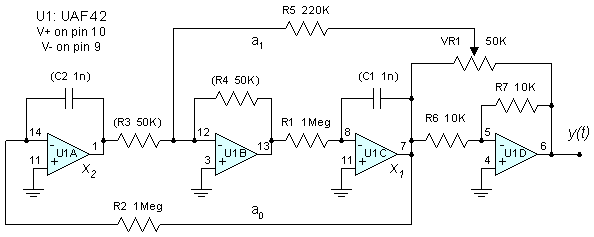
This circuit is paraphrased from an excellent application note4 for the Burr-Brown UAF42 state variable filter. Pin numbers shown are for the UAF42, which I used because it contains precision integrator capacitors, and because it is easily available from Digi-Key. Burr-Brown isn't the only source for analog function circuits. Analog Devices also has a similar line of parts which is available through distribution. Of course, you can breadboard this with any old opamps and capacitors you happen to have available. Parts values shown in parentheses are internal to the UAF42, and would have to be replaced with discrete components if other opamps are used. Opamps like the TL082 and LF353 have performance characteristics similar to the UAF42. With the parts values shown, the circuit will oscillate at around 160 Hz when you set the damping factor slightly negative with VR1. Restore damping factor to zero (VR1 near center of range) to maintain steady oscillation. If you use a 10-turn potentiometer for VR1, you should be able to stabilize output amplitude enough to make a quick distortion measurement. Assuming you aren't at or near clipping, harmonic distortion will be so low as to be unmeasureable.

Now that we've shown that the basic idea works, let's take a look at what attributes would be desired for a general purpose audio oscillator. In the following table I list design goals as well as actual results measured on my prototype, shown above. Spectra were plotted with 10 dB/division on the vertical axis, using an HP3580A.
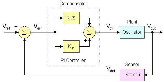
Achieving these goals is not trivial. We often think of a light bulb as the symbol for bright ideas and innovation. In this case however, it will take more than a simple light bulb to achieve the stated goals. Since we are in the mode of analog computation, let's consider the use of a closed loop control system5 to maintain stable sine wave oscillation. To do this I've added a Detector and a Proportional/Integral (PI) Controller to the Oscillator. In some texts, these blocks would be called the Sensor, the Compensator, and the Plant, respectively. The only additional block needed is an error detector, shown below as a summer producing an error voltage which is the difference between a reference voltage and the detector output voltage.
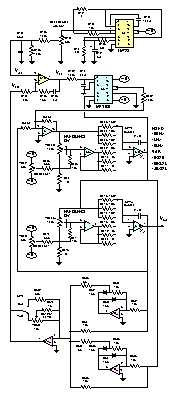 Here you will find a complete detailed schematic diagram of my current prototype with all parts values shown. The only functions not shown are a filtered, bypassed, and regulated +/- 15 Vdc power supply, a balanced line-level output attenuator, and a Red Lion SUB-CUB-R frequency counter, which is available from Digi-Key. I've left these out because their circuits are completely generic and would just add clutter to the important stuff.
Many commercial designs seek to combine two or more functional areas to reduce parts count and manufacturing cost. The ultimate expression of this is the HP200 Audio Oscillator6, 11, in which a simple incandescent light bulb serves as sensor, reference, error detector, compensator, and even provides the gain control feature in the oscillator core. Such designs are of no use to the experimenter and enthusiast however, who would seek to adjust and understand individual parameters within each functional area. I've tried to maintain each function as a separate circuit, with the exception of the PI Controller for which I've used the standard published circuit where a single opamp, U1D, serves as both error detector and compensator.
The oscillator core is implemented using the Burr-Brown UAF42 state variable filter, U4. A range switch, SW1, is added with both fixed and variable settings. All ranges use the UAF42's internal 1nf integrating capacitors, shown in parentheses on the schematic diagram. Since state variable filters are gain tuned, variable frequency is obtained with a simple stereo volume control, VR200, buffered by opamp followers U5A and U5B. I used Radio Shack's part #271-1732C potentiometer which provides logarithmically increasing frequency with clock wise rotation.
There are many ways to convert AC to DC, but most compute the absolute value of an AC input voltage. I've used two precision rectifier circuits12, U1B and U1C, with their outputs summed at the inverting input of an opamp configured for variable gain, U1A. The germanium diodes specified for D301 through D304 are available at Radio Shack, and provide flatter frequency response than silicon diodes such as the 1N914. Both the sine and cosine outputs are detected and summed, for a substantial reduction in detector ripple13.
The choice of compensator determines how much steady state error will be present when the loop is stable. The circuit works fine with just the proportional term which is determined by R108, but flatness suffers at high frequencies. If only the integral term controlled by C103 is present, the output level will be completely unstable regardless of how other controls are set. When both proportional and integral terms are present however, steady state error due to the control loop is completely eliminated with the result that flatness is now controlled strictly by the frequency response of the sensor circuit. If the detector is flat, the oscillator will be too. Another potential source of error is drift over time and temperature of the voltage reference. The LM723 wasn't my first choice for this function, but I had one on hand.
Having both proportional and integral terms also means that the control loop now has dynamic transient behavior, which you can tune and optimize for your application. The controller gain and time constant shown in my prototype are well suited for general purpose bench use, but you can change them to suit other applications. You could even arrange to use different coefficients for different range switch settings. PI controller tuning is a very deep subject indeed, way beyond the scope of this web page7.

A filtered and regulated power supply is installed in the base section. Regulation is provided by standard three-terminal regulators. Line cord, power switch, and fuse holder are mounted on the left side panel under an aluminum shield. The main circuit board is mounted in the top section along with all user controls and connectors. The empty socket in the middle of the oscillator board is for a test jumper, which I used to evaluate control loop performance during construction. Click on the image at left to expand into a new window.
I found in my prototype that high frequency harmonics were leaking from the detector output, U1A pin 1, back into the oscillator causing increased distortion so I rerouted this signal to go directly to the controller, away from other signals. Also, I found 60Hz hum from the power supply transformer was being coupled into the wiring to the range switch, SW1. I fixed this by pulling all of the wires going to and from the range switch into a tight bundle so they didn't form an open loop.
By using Burr-Brown's UAF42 state variable filter for the oscillator core and MPY634 four-quadrant multiplier to control the damping factor of the oscillator, I've pretty much eliminated the normal sources of distortion found in audio oscillators. The distortion that remains appears to come from two sources. First of all, the detector DC output still has some ripple voltage which makes its way back into the oscillator through the controller and multiplier, when the oscillator is set to produce low audio frequencies. Secondly, when variable frequency ranges are selected, the opamp followers produce common mode distortion at high audio frequencies due to the dissimilar impedances seen by the inverting and noninverting inputs. This effect is described in the Burr-Brown OPA134 data sheet8. Both of these problems can be solved, and in fact have been in the HP8903A. Until I decide to make another prototype however, I'll be using the circuit shown above for all my bench testing of audio preamps, mixers, and amplifiers.
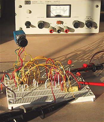
Since completing the prototype described on this page, I have found some additional references and breadboarded a new design which completely transcends the previous version. I've obtained a new solution for the differential equations of a damped oscillator in which the frequency of oscillation no longer depends on damping factor, and have also developed a new automatic level control (ALC) circuit which allows the dynamic behavior of the oscillator to be fully described (and predicted!) with a simple transfer function. Since these new ideas go far beyond the scope of this web page, I've published them in the International Journal of Circuit Theory and Applications14. If you don't have access to the IJCTA and would like to see the article and its references, please send email to the address given in the graphic at the bottom of this page to ask for a pre-print of the article.

